


Product Applications:
A three-chamber thermal shock test chamber (also known as a three-chamber thermal shock chamber, a damper-type thermal shock chamber, or a three-zone temperature shock test chamber) is a specialized environmental reliability testing device that employs three independent chambers—a high-temperature zone, a low-temperature zone, and a test zone—to subject stationary samples to rapid temperature cycling by switching between hot and cold airflows via dampers. It can rapidly switch the environment surrounding the sample from extremely low temperatures (as low as -65°C) to extremely high temperatures (as high as +180°C) within a very short time, simulating the severe thermal shocks products encounter during transportation, storage, and use. This allows for the detection of defects such as cracking, delamination, solder joint failure, deterioration of electrical performance, and seal failure in materials and components under thermal stress.
Core Operating Principle:
The core logic of the three-chamber thermal shock test chamber is as follows: independent temperature control in three zones + pneumatic damper switching. The sample remains stationary throughout the process, and temperature shocks are achieved through airflow switching.
Test Standards:
- GJB 150.5A-2009
- GB/T 2423.22-2012/IEC 60068-2-14:2009
- GB/T 2424.13-2002/IEC 60068-2-33:1971
- GB/T 2423.1-2008/IEC 6008-2-1-2007
- GB/T 2423.2-2008/IEC 60068-2-2:2007
- GJB 360B-2009
- GB/T 10589-2008
- GB/T 11158-2008
- GB/T 5170.2-1996
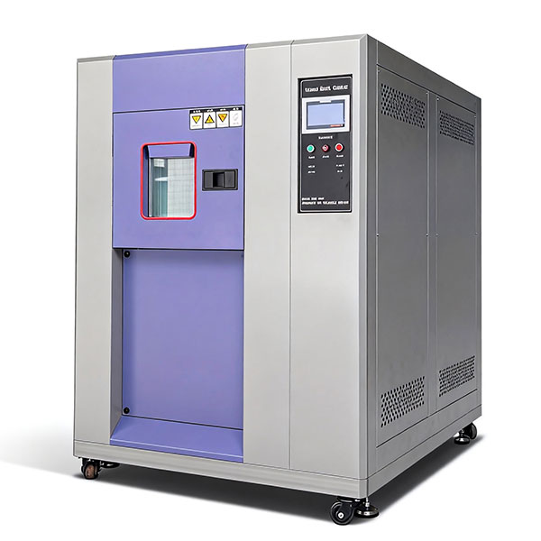
Cabinet Construction:
2.1.1. Inner Cabinet Material: Made of 1.2 mm thick SUS304 stainless steel, cut and processed using high-precision CNC equipment, then bent into shape. Seams are TIG-welded, ground, and polished for a sleek and elegant finish.
2.1.2. Outer Enclosure Material: Made from 1.2mm-thick cold-rolled steel plate, cut and processed using high-precision CNC equipment, then bent into shape. Seams are TIG-welded, ground, and polished, followed by high-temperature powder coating to effectively prevent rust and provide a finished appearance.
2.1.3. Insulation Material: A composite insulation layer made of high-temperature-resistant fiberglass wool and rigid polyurethane foam, providing excellent thermal insulation.
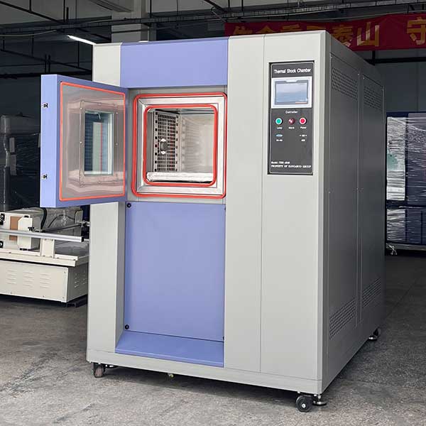
2.1.4. Sample Racks: Two SUS304 stainless steel grid-style shelves (load capacity ≤ 25 kg per shelf), with adjustable spacing of 40 mm.
2.1.5. Cable Access Port: A Φ50mm access port is provided on the left side of the test chamber, equipped with corresponding thermal insulation accessories and a dedicated sealing plug.
2.1.6. Control Panel: LCD touchscreen programmable controller, featuring a main power switch, honey extractor control, lighting switch, USB communication port, and RS-232 communication port.
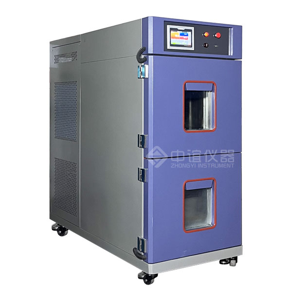
2.1.7. Chamber Doors: Separate single-door access to the preheating chamber, precooling chamber, and test chamber; explosion-proof handles; silicone gaskets to ensure a leak-free seal.
2.1.8. Air Dampers: The air dampers are constructed from SUS304 stainless steel as movable small doors. These doors are fitted with silicone sealing strips and thermal insulation layers. The inner side of the doors uses epoxy resin panels for thermal insulation, effectively preventing heat transfer between chambers. The doors are operated by pneumatic cylinders for switching, with automatic cycle control for simple operation.
2.1.9. Thermal Barrier: Thickened insulation layers are used to provide thermal separation between the preheating chamber, precooling chamber, ambient temperature shock chamber, and test chamber. High-temperature-resistant epoxy resin panels are used at the joints to effectively prevent heat transfer between chambers, achieving energy-saving objectives. Additionally, the inner panels of the doors for the preheating chamber, precooling chamber, and test chamber are all made of epoxy resin panels to prevent heat from transferring to the exterior of the equipment, which could affect the temperature of the installed components, ensuring safety and reliability.
2.1.10. Exhaust Duct: An exhaust duct is installed at the top of the equipment and can be connected to the outdoors to prevent temperature fluctuations during high- and low-temperature shocks from affecting the temperature of the installation space.
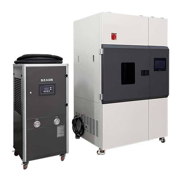
2.1.11. Air Circulation Ducts: The preheating chamber is equipped with a heater, circulation fan, internal circulation ducts, temperature sensors, and dampers; the pre-cooling chamber is equipped with a refrigeration evaporator, cold storage plates, a heater, circulation fan, internal circulation ducts, temperature sensors, and dampers; The ambient temperature shock chamber is equipped with a blower, dampers, and an exhaust pipe; the test chamber is equipped with a perforated air distribution plate, sample trays, tray indexing racks, and temperature sensors. During the pre-cooling and pre-heating phases, the ambient temperature shock zone remains inactive, while the high-temperature and low-temperature zones operate in internal circulation to rapidly bring the air temperatures in the pre-heating and pre-cooling zones to the preset values; the shock test can begin from either the high-temperature or low-temperature zone as required. During high-temperature shock testing, the preheating zone dampers are controlled by signals from the controller. The airflow passes through the perforated air distribution plate in the test chamber and the test samples before returning to the preheating zone. At this time, the ambient temperature shock zone is inactive, and the low-temperature zone operates in internal circulation; During low-temperature shock testing, the pre-cooling zone damper is controlled by instructions from the controller. The airflow passes through the perforated plate of the test work area and the test specimen before returning to the pre-cooling zone. At this time, the ambient-temperature shock zone is inactive, and the high-temperature zone performs internal circulation; During ambient temperature shock testing, the controller sends commands to operate the ambient temperature shock zone dampers and blower. The blower draws air from the equipment installation space, directs it through the perforated air distribution plate and the test specimen in the test chamber, and simultaneously exhausts the hot or cold airflow from the test chamber to the outside. At this time, the high-temperature and low-temperature zones operate in internal circulation. Multiple-cycle automatic control can be configured as required, thereby achieving rapid temperature cycling and uniform temperature distribution within the chamber.
2.1.12. Chamber Design Features: The equipment is designed as a monolithic structure. The upper front section houses the test chamber, the lower front section houses the preheating chamber, the upper rear section houses the precooling chamber, and the lower rear section houses the mechanical room for the refrigeration unit. The ambient temperature shock circulation duct and supply fan are installed on the top of the equipment, and the electrical control cabinet is located on the right side. The bottom of the unit is equipped with casters and locking feet to facilitate movement and positioning. The preheating chamber, precooling chamber, ambient temperature shock chamber, and test chamber are interconnected via adjustable dampers, enabling rapid temperature cycling while minimizing the footprint and optimizing space utilization.
Control System:
2.2.1. Equipped with a well-known LCD programmable temperature controller. Capable of performing programmed tests, supporting multi-group and multi-segment programming, and offering the flexibility to select between fixed-value and program modes with freely adjustable time settings.
2.2.2. Intelligent digital PID microprocessor-based temperature control instrument.
2.2.3. Touchscreen control with touch-based settings, digital display, and direct readout; temperature sensors use PT100/platinum resistance thermometers.
2.2.4. Temperature control employs a thermal equilibrium method.
2.2.5. Major electrical components of the equipment, such as circuit breakers, AC contactors, and small relays, are all sourced from well-known domestic and international brands.
2.2.6. Convenient data processing: Can be connected to a printer or a RS-232 communication interface; features a USB data transfer port (for flash drives); allows for computer display and printing of temperature and time curves, providing a reliable guarantee for data storage and playback during the testing process.

 豫公网安备41032502000206号


